Dinobell Antenna Solutions
Antenna Overview
February 1, 2019
Antennas are required by any radio receiver or transmitter to couple its electrical connection to the electromagnetic field.Radio waves are electromagnetic waves which carry signals through the air (or through space) at the speed of light with almost no transmission loss.
Antennas can be classified as omnidirectional, radiating energy approximately equally in all directions, or directional, where energy radiates more along one direction than others. (Antennas are reciprocal, so the same effect occurs for reception of radio waves.) A completely uniform omnidirectional antenna is not physically possible. Some antenna types have a uniform radiation pattern in the horizontal plane, but send little energy upward or downward. A “directional” antenna usually is intended to maximize its coupling to the electromagnetic field in the direction of the other station.
A vertical antenna or whip antenna radiates in all directions horizontally, but sends less energy upward or downward. Similarly, a dipole antenna oriented horizontally sends little energy in direction vectors parallel to the conductor; this region is called the antenna null.
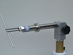
Half-wave dipole antenna
The dipole antenna, which is the basis for most antenna designs, is a balanced component, with equal but opposite voltages and currents applied at its two terminals. The vertical antenna is a monopole antenna, not balanced with respect to ground. The ground (or any large conductive surface) plays the role of the second conductor of a dipole. Since monopole antennas rely on a conductive surface, they may be mounted with a ground plane to approximate the effect of being mounted on the Earth’s surface.
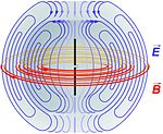
Diagram of the electric fields (blue) and magnetic fields (red) radiated by a dipole antenna (black rods) during transmission.
More complex antennas increase the directivity of the antenna. Additional elements in the antenna structure, which need not be directly connected to the receiver or transmitter, increase its directionality. Antenna “gain” describes the concentration of radiated power into a particular solid angle of space. “Gain” is perhaps an unfortunately chosen term, by comparison with amplifier “gain” which implies a net increase in power. In contrast, for antenna “gain”, the power increased in the desired direction is at the expense of power reduced in undesired directions. Unlike amplifiers, antennas are electrically “passive” devices which conserve total power, and there is no increase in total power above that delivered from the power source (the transmitter), only improved distribution of that fixed total.
A phased array consists of two or more simple antennas which are connected together through an electrical network. This often involves a number of parallel dipole antennas with a certain spacing. Depending on the relative phase introduced by the network, the same combination of dipole antennas can operate as a “broadside array” (directional normal to a line connecting the elements) or as an “end-fire array” (directional along the line connecting the elements). Antenna arrays may employ any basic (omnidirectional or weakly directional) antenna type, such as dipole, loop or slot antennas. These elements are often identical.
A log-periodic dipole array consists of a number of dipole elements of different lengths in order to obtain a somewhat directional antenna having an extremely wide bandwidth. The dipole antennas composing it are all considered “active elements” since they are all electrically connected together (and to the transmission line). A Yagi–Uda antenna (or simply “Yagi”), has only one dipole element with an electrical connection; the other parasitic elements interact with the electromagnetic field in order to realize a directional antenna over a narrow bandwidth. There may be a number of so-called “directors” in front of the active element in the direction of propagation, and one or more “reflectors” on the opposite side of the active element.
Greater directionality can be obtained using beam-forming techniques such as a parabolic reflector or a horn. Since high directivity in an antenna depends on it being large compared to the wavelength, narrow beams of this type are more easily achieved at UHF and microwave frequencies.
At low frequencies (such as AM broadcast), arrays of vertical towers are used to achieve directionality[9] and they will occupy large areas of land. For reception, a long Beverage antenna can have significant directivity. For non directional portable use, a short vertical antenna or small loop antenna works well, with the main design challenge being that of impedance matching. With a vertical antenna a loading coil at the base of the antenna may be employed to cancel the reactive component of impedance; small loop antennas are tuned with parallel capacitors for this purpose.
An antenna lead-in is the transmission line, or feed line, which connects the antenna to a transmitter or receiver. The “antenna feed” may refer to all components connecting the antenna to the transmitter or receiver, such as an impedance matching network in addition to the transmission line. In a so-called “aperture antenna”, such as a horn or parabolic dish, the “feed” may also refer to a basic radiating antenna embedded in the entire system of reflecting elements (normally at the focus of the parabolic dish or at the throat of a horn) which could be considered the one active element in that antenna system. A microwave antenna may also be fed directly from a waveguide in place of a (conductive) transmission line.
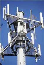
Cell phone base station antennas
An antenna counterpoise, or ground plane, is a structure of conductive material which improves or substitutes for the ground. It may be connected to or insulated from the natural ground. In a monopole antenna, this aids in the function of the natural ground, particularly where variations (or limitations) of the characteristics of the natural ground interfere with its proper function. Such a structure is normally connected to the return connection of an unbalanced transmission line such as the shield of a coaxial cable.
An electromagnetic wave refractor in some aperture antennas is a component which due to its shape and position functions to selectively delay or advance portions of the electromagnetic wavefront passing through it. The refractor alters the spatial characteristics of the wave on one side relative to the other side. It can, for instance, bring the wave to a focus or alter the wave front in other ways, generally in order to maximize the directivity of the antenna system. This is the radio equivalent of an optical lens.
An antenna coupling network is a passive network (generally a combination of inductive and capacitive circuit elements) used for impedance matching in between the antenna and the transmitter or receiver. This may be used to improve the standing wave ratio in order to minimize losses in the transmission line and to present the transmitter or receiver with a standard resistive impedance that it expects to see for optimum operation.
[from wikipedia]
Maybe you like also
Copy©2023 | Shenzhen Dinobell Communication Co.,Ltd.