Dinobell Antenna Solutions
Effect of Ground
March 4, 2019
Effect of Ground
Ground reflections is one of the common types of multipath.
The radiation pattern and even the driving point impedance of an antenna can be influenced by the dielectric constant and especially conductivity of nearby objects. For a terrestrial antenna, the ground is usually one such object of importance. The antenna’s height above the ground, as well as the electrical properties (permittivity and conductivity) of the ground, can then be important. Also, in the particular case of a monopole antenna, the ground (or an artificial ground plane) serves as the return connection for the antenna current thus having an additional effect, particularly on the impedance seen by the feed line.
When an electromagnetic wave strikes a plane surface such as the ground, part of the wave is transmitted into the ground and part of it is reflected, according to the Fresnel coefficients. If the ground is a very good conductor then almost all of the wave is reflected (180° out of phase), whereas a ground modeled as a (lossy) dielectric can absorb a large amount of the wave’s power. The power remaining in the reflected wave, and the phase shift upon reflection, strongly depend on the wave’s angle of incidence and polarization. The dielectric constant and conductivity (or simply the complex dielectric constant) is dependent on the soil type and is a function of frequency.
For very low frequencies to high frequencies (< 30 MHz), the ground behaves as a lossy dielectric,thus the ground is characterized both by a conductivity and permittivity (dielectric constant) which can be measured for a given soil (but is influenced by fluctuating moisture levels) or can be estimated from certain maps. At lower frequencies the ground acts mainly as a good conductor, which AM middle wave broadcast (0.5–1.6 MHz) antennas depend on.
At frequencies between 3 and 30 MHz, a large portion of the energy from a horizontally polarized antenna reflects off the ground, with almost total reflection at the grazing angles important for ground wave propagation. That reflected wave, with its phase reversed, can either cancel or reinforce the direct wave, depending on the antenna height in wavelengths and elevation angle (for a sky wave).
On the other hand, vertically polarized radiation is not well reflected by the ground except at grazing incidence or over very highly conducting surfaces such as sea water.However the grazing angle reflection important for ground wave propagation, using vertical polarization, is in phase with the direct wave, providing a boost of up to 6 dB, as is detailed below.
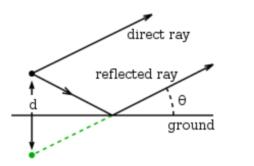
The wave reflected by earth can be considered as emitted by the image antenna.
At VHF and above (> 30 MHz) the ground becomes a poorer reflector. However it remains a good reflector especially for horizontal polarization and grazing angles of incidence. That is important as these higher frequencies usually depend on horizontal line-of-sight propagation (except for satellite communications), the ground then behaving almost as a mirror.
The net quality of a ground reflection depends on the topography of the surface. When the irregularities of the surface are much smaller than the wavelength, the dominant regime is that of specular reflection, and the receiver sees both the real antenna and an image of the antenna under the ground due to reflection. But if the ground has irregularities not small compared to the wavelength, reflections will not be coherent but shifted by random phases. With shorter wavelengths (higher frequencies), this is generally the case.
Whenever both the receiving or transmitting antenna are placed at significant heights above the ground (relative to the wavelength), waves specularly reflected by the ground will travel a longer distance than direct waves, inducing a phase shift which can sometimes be significant. When a sky wave is launched by such an antenna, that phase shift is always significant unless the antenna is very close to the ground (compared to the wavelength).
The phase of reflection of electromagnetic waves depends on the polarization of the incident wave. Given the larger refractive index of the ground (typically n ≈ 2) compared to air (n = 1), the phase of horizontally polarized radiation is reversed upon reflection (a phase shift of pi radians or 180°). On the other hand, the vertical component of the wave’s electric field is reflected at grazing angles of incidence approximately in phase. These phase shifts apply as well to a ground modeled as a good electrical conductor.
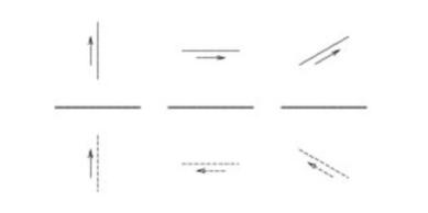
The currents in an antenna appear as an image in opposite phase when reflected at grazing angles. This causes a phase reversal for waves emitted by a horizontally polarized antenna (left) but not a vertically polarized antenna (center).
This means that a receiving antenna “sees” an image of the antenna but with reversed currents. That current is in the same absolute direction as the actual antenna if the antenna is vertically oriented (and thus vertically polarized) but opposite the actual antenna if the antenna current is horizontal.
The actual antenna which is transmitting the original wave then also may receive a strong signal from its own image from the ground. This will induce an additional current in the antenna element, changing the current at the feedpoint for a given feedpoint voltage. Thus the antenna’s impedance, given by the ratio of feedpoint voltage to current, is altered due to the antenna’s proximity to the ground. This can be quite a significant effect when the antenna is within a wavelength or two of the ground. But as the antenna height is increased, the reduced power of the reflected wave (due to the inverse square law) allows the antenna to approach its asymptotic feedpoint impedance given by theory. At lower heights, the effect on the antenna’s impedance is very sensitive to the exact distance from the ground, as this affects the phase of the reflected wave relative to the currents in the antenna. Changing the antenna’s height by a quarter wavelength, then changes the phase of the reflection by 180°, with a completely different effect on the antenna’s impedance.
The ground reflection has an important effect on the net far field radiation pattern in the vertical plane, that is, as a function of elevation angle, which is thus different between a vertically and horizontally polarized antenna. Consider an antenna at a height h above the ground, transmitting a wave considered at the elevation angle θ. For a vertically polarized transmission the magnitude of the electric field of the electromagnetic wave produced by the direct ray plus the reflected ray is:
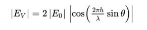
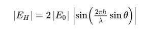
Thus the power received can be as high as 4 times that due to the direct wave alone (such as when θ = 0), following the square of the cosine. The sign inversion for the reflection of horizontally polarized emission instead results in:
where:
E0 is the electrical field that would be received by the direct wave if there were no ground.
θ is the elevation angle of the wave being considered.
λ is the wavelength.
h the height of the antenna (half the distance between the antenna and its image).
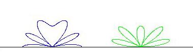
Radiation patterns of antennas and their images reflected by the ground. At left the polarization is vertical and there is always a maximum for θ=0. If the polarization is horizontal as at right, there is always a zero for θ=0.
For horizontal propagation between transmitting and receiving antennas situated near the ground reasonably far from each other, the distances traveled by the direct and reflected rays are nearly the same. There is almost no relative phase shift. If the emission is polarized vertically, the two fields (direct and reflected) add and there is maximum of received signal. If the signal is polarized horizontally, the two signals subtract and the received signal is largely cancelled. The vertical plane radiation patterns are shown in the image at right. With vertical polarization there is always a maximum for θ = 0, horizontal propagation (left pattern). For horizontal polarization, there is cancellation at that angle. Note that the above formulae and these plots assume the ground as a perfect conductor. These plots of the radiation pattern correspond to a distance between the antenna and its image of 2.5 λ . As the antenna height is increased, the number of lobes increases as well.
The difference in the above factors for the case of θ = 0 is the reason that most broadcasting (transmissions intended for the public) uses vertical polarization. For receivers near the ground, horizontally polarized transmissions suffer cancellation. For best reception the receiving antennas for these signals are likewise vertically polarized. In some applications where the receiving antenna must work in any position, as in mobile phones, the base station antennas use mixed polarization, such as linear polarization at an angle (with both vertical and horizontal components) or circular polarization.
On the other hand, analog television transmissions are usually horizontally polarized, because in urban areas buildings can reflect the electromagnetic waves and create ghost images due to multipath propagation. Using horizontal polarization, ghosting is reduced because the amount of reflection in the horizontal polarization off the side of a building is generally less than in the vertical direction. Vertically polarized analog television have been used in some rural areas. In digital terrestrial television such reflections are less problematic, due to robustness of binary transmissions and error correction.
Maybe you like also
Copy©2023 | Shenzhen Dinobell Communication Co.,Ltd.