Dinobell Antenna Solutions
Introduce of Antenna and Aerial
October 11, 2018
Introduce of Antenna and Aerial
In radio engineering, an antenna is the interface between radio waves propagating through space and electric currents moving in metal conductors, used with a transmitter or receiver.In transmission, a radio transmitter supplies an electric current to the antenna’s terminals, and the antenna radiates the energy from the current as electromagnetic waves (radio waves). In reception, an antenna intercepts some of the power of a radio wave in order to produce an electric current at its terminals, that is applied to a receiver to be amplified. Antennas are essential components of all radio equipment.
An antenna is an array of conductors (elements), electrically connected to the receiver or transmitter. Antennas can be designed to transmit and receive radio waves in all horizontal directions equally (omnidirectional antennas), or preferentially in a particular direction (directional, or high-gain, or “beam” antennas). An antenna may include components not connected to the transmitter, parabolic reflectors, horns, or parasitic elements, which serve to direct the radio waves into a beam or other desired radiation pattern.
The first antennas were built in 1888 by German physicist Heinrich Hertz in his pioneering experiments to prove the existence of waves predicted by the electromagnetic theory of James Clerk Maxwell. Hertz placed dipole antennas at the focal point of parabolic reflectors for both transmitting and receiving. Starting in 1895, Guglielmo Marconi began development of antennas practical for long-distance, wireless telegraphy, for which he received a Nobel Prize.
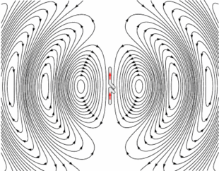
Animation of a half-wave dipole antenna transmitting radio waves, showing the electric field lines. The antenna in the center is two vertical metal rods, with an alternating current applied at its center from a radio transmitter (not shown). The voltage charges the two sides of the antenna alternately positive (+) and negative (−). Loops of electric field (black lines) leave the antenna and travel away at the speed of light; these are the radio waves.
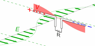
Animated diagram of a half-wave dipole antenna receiving energy from a radio wave. The antenna consists of two metal rods connected to a receiver R. The electric field (E, green arrows) of the incoming wave pushes the electrons in the rods back and forth, charging the ends alternately positive (+) and negative (−). Since the length of the antenna is one half the wavelength of the wave, the oscillating field induces standing waves of voltage (V, represented by red band) and current in the rods. The oscillating currents (black arrows) flow down the transmission line and through the receiver (represented by the resistance R).
[from wikipedia]
Maybe you like also
Copy©2023 | Shenzhen Dinobell Communication Co.,Ltd.