Dinobell Antenna Solutions
Key Characteristics of Antenna
February 2, 2019
Key Characteristics of Antenna
It is a fundamental property of antennas that the electrical characteristics of an antenna , such as gain, radiation pattern, impedance, bandwidth, resonant frequency and polarization, are the same whether the antenna is transmitting or receiving. For example, the “receiving pattern” (sensitivity as a function of direction) of an antenna when used for reception is identical to the radiation pattern of the antenna when it is driven and functions as a radiator. This is a consequence of the reciprocity theorem of electromagnetics. Therefore, in discussions of antenna properties no distinction is usually made between receiving and transmitting terminology, and the antenna can be viewed as either transmitting or receiving, whichever is more convenient.
A necessary condition for the aforementioned reciprocity property is that the materials in the antenna and transmission medium are linear and reciprocal. Reciprocal (or bilateral) means that the material has the same response to an electric current or magnetic field in one direction, as it has to the field or current in the opposite direction. Most materials used in antennas meet these conditions, but some microwave antennas use high-tech components such as isolators and circulators, made of nonreciprocal materials such as ferrite. These can be used to give the antenna a different behavior on receiving than it has on transmitting, which can be useful in applications like radar.
The antenna’s power gain (or simply “gain”) also takes into account the antenna’s efficiency, and is often the primary figure of merit. Antennas are characterized by a number of performance measures which a user would be concerned with in selecting or designing an antenna for a particular application. A plot of the directional characteristics in the space surrounding the antenna is its radiation pattern.
Bandwidth
The frequency range or bandwidth over which an antenna functions well can be very wide (as in a log-periodic antenna) or narrow (as in a small loop antenna); outside this range the antenna impedance becomes a poor match to the transmission line and transmitter (or receiver). Use of the antenna well away from its design frequency affects its radiation pattern, reducing its directive gain.
Generally an antenna will not have a feed-point impedance that matches that of a transmission line; a matching network between antenna terminals and the transmission line will improve power transfer to the antenna. The matching network may also limit the usable bandwidth of the antenna system. It may be desirable to use tubular elements, instead of thin wires, to make an antenna; these will allow a greater bandwidth. Or, several thin wires can be grouped in a cage to simulate a thicker element. This widens the bandwidth of the resonance.
Amateur radio antennas that operate at several frequency bands which are widely separated from each other may connect elements resonant at those different frequencies in parallel. Most of the transmitter’s power will flow into the resonant element while the others present a high impedance. Another solution uses traps, parallel resonant circuits which are strategically placed in breaks along each antenna element. When used at one particular frequency band the trap presents a very high impedance (parallel resonance) effectively truncating the element at that length, making it a proper resonant antenna. At a lower frequency the trap allows the full length of the element to be employed, albeit with a shifted resonant frequency due to the inclusion of the trap’s net reactance at that lower frequency.
The bandwidth characteristics of a resonant antenna element can be characterized according to its Q where the resistance involved is the radiation resistance, which represents the emission of energy from the resonant antenna to free space.
The Q of a narrow band antenna can be as high as 15. On the other hand, the reactance at the same off-resonant frequency of one using thick elements is much less, consequently resulting in a Q as low as 5. These two antennas may perform equivalently at the resonant frequency, but the second antenna will perform over a bandwidth 3 times as wide as the antenna consisting of a thin conductor.
Antennas for use over much broader frequency ranges are achieved using further techniques. Adjustment of a matching network can, in principle, allow for any antenna to be matched at any frequency. Thus the small loop antenna built into most AM broadcast (medium wave) receivers has a very narrow bandwidth, but is tuned using a parallel capacitance which is adjusted according to the receiver tuning. On the other hand, log-periodic antennas are not resonant at any frequency but can be built to attain similar characteristics (including feedpoint impedance) over any frequency range. These are therefore commonly used (in the form of directional log-periodic dipole arrays) as television antennas.
Gain
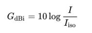
Gain is a parameter which measures the degree of directivity of the antenna’s radiation pattern. A high gain antenna will radiate most of its power in a particular direction, while a low-gain antenna will radiate over a wide angle. The antenna gain, or power gain of an antenna is defined as the ratio of the intensity (power per unit surface area) {\displaystyle \scriptstyle I} radiated by the antenna in the direction of its maximum output, at an arbitrary distance, divided by the intensity {\displaystyle \scriptstyle I_{\text{iso}}} radiated at the same distance by a hypothetical isotropic antenna which radiates equal power in all directions. This dimensionless ratio is usually expressed logarithmically in decibels, these units are called “decibels-isotropic” (dBi)
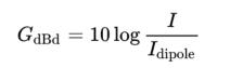
A second unit used to measure gain is the ratio of the power radiated by the antenna to the power radiated by a half-wave dipole antenna {\displaystyle \scriptstyle I_{\text{dipole}}}; these units are called “decibels-dipole” (dBd)
Since the gain of a half-wave dipole is 2.15 dBi and the logarithm of a product is additive, the gain in dBi is just 2.15 decibels greater than the gain in dBd
![]()
High-gain antennas have the advantage of longer range and better signal quality, but must be aimed carefully at the other antenna. An example of a high-gain antenna is a parabolic dish such as a satellite television antenna. Low-gain antennas have shorter range, but the orientation of the antenna is relatively unimportant. An example of a low-gain antenna is the whip antenna found on portable radios and cordless phones. Antenna gain should not be confused with amplifier gain, a separate parameter measuring the increase in signal power due to an amplifying device placed at the front-end of the system, such as a low-noise amplifier.
Effective area or aperture
The effective area or effective aperture of a receiving antenna expresses the portion of the power of a passing electromagnetic wave which the antenna delivers to its terminals, expressed in terms of an equivalent area. For instance, if a radio wave passing a given location has a flux of 1 pW / m2 (10−12 Watts per square meter) and an antenna has an effective area of 12 m2, then the antenna would deliver 12 pW of RF power to the receiver (30 microvolts RMS at 75 Ohms). Since the receiving antenna is not equally sensitive to signals received from all directions, the effective area is a function of the direction to the source.
Due to reciprocity (discussed above) the gain of an antenna used for transmitting must be proportional to its effective area when used for receiving. Consider an antenna with no loss, that is, one whose electrical efficiency is 100%. It can be shown that its effective area averaged over all directions must be equal to λ2/4π, the wavelength squared divided by 4π. Gain is defined such that the average gain over all directions for an antenna with 100% electrical efficiency is equal to 1. Therefore, the effective area Aeff in terms of the gain G in a given direction is given by:
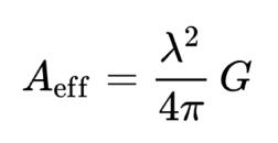
For an antenna with an efficiency of less than 100%, both the effective area and gain are reduced by that same amount. Therefore, the above relationship between gain and effective area still holds. These are thus two different ways of expressing the same quantity. Aeff is especially convenient when computing the power that would be received by an antenna of a specified gain, as illustrated by the above example.
Radiation pattern
Polar plots of the horizontal cross sections of a (virtual) Yagi-Uda-antenna. Outline connects points with 3 dB field power compared to an ISO emitter.
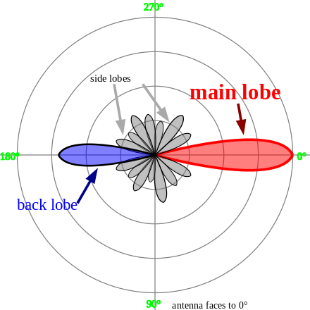
The radiation pattern of an antenna is a plot of the relative field strength of the radio waves emitted by the antenna at different angles in the far-field. It is typically represented by a three-dimensional graph, or polar plots of the horizontal and vertical cross sections. The pattern of an ideal isotropic antenna, which radiates equally in all directions, would look like a sphere. Many nondirectional antennas, such as monopoles and dipoles, emit equal power in all horizontal directions, with the power dropping off at higher and lower angles; this is called an omnidirectional pattern and when plotted looks like a torus or donut.
The radiation of many antennas shows a pattern of maxima or “lobes” at various angles, separated by “nulls”, angles where the radiation falls to zero. This is because the radio waves emitted by different parts of the antenna typically interfere, causing maxima at angles where the radio waves arrive at distant points in phase, and zero radiation at other angles where the radio waves arrive out of phase. In a directional antenna designed to project radio waves in a particular direction, the lobe in that direction is designed larger than the others and is called the “main lobe”. The other lobes usually represent unwanted radiation and are called “sidelobes”. The axis through the main lobe is called the “principal axis” or “boresight axis”.
The polar diagrams (and therefore the efficiency and gain) of Yagi antennas are tighter if the antenna is tuned for a narrower frequency range, e.g. the grouped antenna compared to the wideband. Similarly, the polar plots of horizontally polarized yagis are tighter than for those vertically polarized .
Field regions
The space surrounding an antenna can be divided into three concentric regions: The reactive near-field (also called the inductive near-field), the radiating near-field (Fresnel region) and the far-field (Fraunhofer) regions. These regions are useful to identify the field structure in each, although there are no precise boundaries.
The far-field region is far enough from the antenna to ignore its size and shape: It can be assumed that the electromagnetic wave is purely a radiating plane wave (electric and magnetic fields are in phase and perpendicular to each other and to the direction of propagation). This simplifies the mathematical analysis of the radiated field.
Efficiency
Efficiency of a transmitting antenna is the ratio of power actually radiated (in all directions) to the power absorbed by the antenna terminals. The power supplied to the antenna terminals which is not radiated is converted into heat. This is usually through loss resistance in the antenna’s conductors, or loss between the reflector and feed horn of a parabolic antenna.
Antenna efficiency is separate from impedance matching, which may also reduce the amount of power radiated using a given transmitter. If an SWR meter reads 150 W of incident power and 50 W of reflected power, that means 100 W have actually been absorbed by the antenna (ignoring transmission line losses). How much of that power has actually been radiated cannot be directly determined through electrical measurements at (or before) the antenna terminals, but would require (for instance) careful measurement of field strength. The loss resistance and efficiency of an antenna can be calculated.
The loss resistance will generally affect the feedpoint impedance, adding to its resistive component. That resistance will consist of the sum of the radiation resistance Rr and the loss resistance Rloss. If a current I is delivered to the terminals of an antenna, then a power of I2 Rr will be radiated and a power of I2 Rloss will be lost as heat. Therefore, the efficiency of an antenna is equal to Rr⁄(Rr + Rloss). Only the total resistance Rr + Rloss can be directly measured.
According to reciprocity, the efficiency of an antenna used as a receiving antenna is identical to the efficiency as defined above. The power that an antenna will deliver to a receiver (with a proper impedance match) is reduced by the same amount. In some receiving applications, the very inefficient antennas may have little impact on performance. At low frequencies, for example, atmospheric or man-made noise can mask antenna inefficiency. For example, CCIR Rep. 258-3 indicates man-made noise in a residential setting at 40 MHz is about 28 dB above the thermal noise floor. Consequently, an antenna with a 20 dB loss (due to inefficiency) would have little impact on system noise performance. The loss within the antenna will affect the intended signal and the noise/interference identically, leading to no reduction in signal to noise ratio (SNR).
Antennas which are not a significant fraction of a wavelength in size are inevitably inefficient due to their small radiation resistance. AM broadcast radios include a small loop antenna for reception which has an extremely poor efficiency. This has little effect on the receiver’s performance, but simply requires greater amplification by the receiver’s electronics. Contrast this tiny component to the massive and very tall towers used at AM broadcast stations for transmitting at the very same frequency, where every percentage point of reduced antenna efficiency entails a substantial cost.
The definition of antenna gain or power gain already includes the effect of the antenna’s efficiency. Therefore, if one is trying to radiate a signal toward a receiver using a transmitter of a given power, one need only compare the gain of various antennas rather than considering the efficiency as well. This is likewise true for a receiving antenna at very high (especially microwave) frequencies, where the point is to receive a signal which is strong compared to the receiver’s noise temperature. However, in the case of a directional antenna used for receiving signals with the intention of rejecting interference from different directions, one is no longer concerned with the antenna efficiency, as discussed above. In this case, rather than quoting the antenna gain, one would be more concerned with the directive gain, or simply directivity which does not include the effect of antenna (in)efficiency. The directive gain of an antenna can be computed from the published gain divided by the antenna’s efficiency. In equation form, gain = directivity × efficiency.
Polarization
The polarization of an antenna refers to the orientation of the electric field (E-plane) of the radio wave with respect to the Earth’s surface and is determined by the physical structure of the antenna and by its orientation. A simple straight wire antenna will have one polarization when mounted vertically, and a different polarization when mounted horizontally.
Reflections generally affect polarization. Radio waves reflected off the ionosphere can change the wave’s polarization. For line-of-sight communications or ground wave propagation, horizontally or vertically polarized transmissions generally remain in about the same polarization state at the receiving location. Matching the receiving antenna’s polarization to that of the transmitter can make a very substantial difference in received signal strength.
Polarization is predictable from an antenna’s geometry. An antenna’s linear polarization is generally along the direction (as viewed from the receiving location) of the antenna’s currents when such a direction can be defined. For instance, a vertical whip antenna will transmit and receive in the vertical polarization. Antennas with horizontal elements are horizontally polarized. Even when the antenna system has a vertical orientation, such as an array of horizontal dipole antennas, the polarization is in the horizontal direction corresponding to the current flow. The polarization of a commercial antenna is an essential specification.
In the most general case, polarization is elliptical, meaning that the polarization of the radio waves varies over time. Two special cases are linear polarization (the ellipse collapses into a line) as discussed above, and circular polarization (in which the two axes of the ellipse are equal). In linear polarization the electric field of the radio wave oscillates back and forth along one direction. In circular polarization, the electric field of the radio wave rotates at the radio frequency circularly around the axis of propagation. Circular or elliptically polarized radio waves are designated as right-handed or left-handed using the “thumb in the direction of the propagation” rule. For circular polarization, optical researchers use the opposite right hand rule from the one used by radio engineers.
It is best for the receiving antenna to match the polarization of the transmitted wave for optimum reception. Intermediate matchings will lose some signal strength, but not as much as a complete mismatch. A circularly polarized antenna can be used to equally well match vertical or horizontal linear polarizations. Transmission from a circularly polarized antenna received by a linearly polarized antenna entails a 3 dB reduction in signal-to-noise ratio as the received power has been cut in half.
Impedance matching
Maximum power transfer requires matching the impedance of an antenna system (as seen looking into the transmission line) to the complex conjugate of the impedance of the receiver or transmitter. In the case of a transmitter, however, the desired matching impedance might not correspond to the dynamic output impedance of the transmitter as analyzed as a source impedance but rather the design value (typically 50 Ohms) required for efficient and safe operation of the transmitting circuitry. The intended impedance is normally resistive but a transmitter (and some receivers) may have additional adjustments to cancel a certain amount of reactance in order to “tweak” the match. When a transmission line is used in between the antenna and the transmitter (or receiver) one generally would like an antenna system whose impedance is resistive and near the characteristic impedance of that transmission line in order to minimize the standing wave ratio (SWR) and the increase in transmission line losses it entails, in addition to matching the impedance that the transmitter (or receiver) expects.
Antenna tuning generally refers to cancellation of any reactance seen at the antenna terminals, leaving only a resistive impedance which might or might not be exactly the desired impedance (that of the transmission line). Although an antenna may be designed to have a purely resistive feedpoint impedance (such as a dipole 97% of a half wavelength long) this might not be exactly true at the frequency that it is eventually used at. In some cases the physical length of the antenna can be “trimmed” to obtain a pure resistance. On the other hand, the addition of a series inductance or parallel capacitance can be used to cancel a residual capacitative or inductive reactance, respectively.
In some cases this is done in a more extreme manner, not simply to cancel a small amount of residual reactance, but to resonate an antenna whose resonance frequency is quite different from the intended frequency of operation. For instance, a “whip antenna” can be made significantly shorter than 1⁄4 wavelength long, for practical reasons, and then resonated using a so-called loading coil. This physically large inductor at the base of the antenna has an inductive reactance which is the opposite of the capacitative reactance that such a vertical antenna has at the desired operating frequency. The result is a pure resistance seen at feedpoint of the loading coil; that resistance is somewhat lower than would be desired to match commercial coax.[citation needed]
An additional problem is matching the remaining resistive impedance to the characteristic impedance of the transmission line. A general matching network will have at least two adjustable elements to correct both components of impedance. Matching networks will have losses, and power restrictions when used for transmitting. Commercial antennas are generally designed to get an approximate match to standard coaxial cables. Antennas based on the dipole may include a balun.
Another extreme case of impedance matching occurs when using a small loop antenna (usually, but not always, for receiving) at a relatively low frequency where it appears almost as a pure inductor. Resonating such an inductor with a capacitor at the frequency of operation not only cancels the reactance but greatly magnifies the very small radiation resistance of such a loop.[citation needed] This is implemented in most AM broadcast receivers, with a small ferrite loop antenna resonated by a capacitor which is varied along with the receiver tuning in order to maintain resonance over the AM broadcast band
[from wikipedia]
Maybe you like also
Copy©2023 | Shenzhen Dinobell Communication Co.,Ltd.